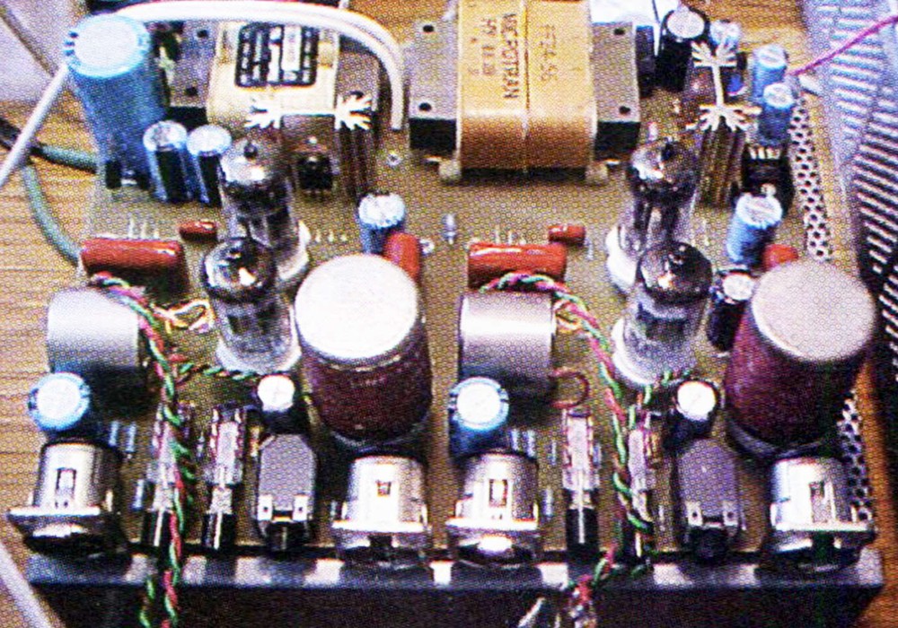
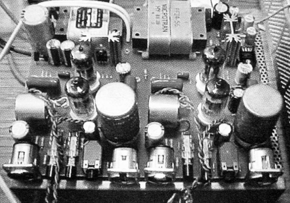
When asked to come up with a "do it yourself" tube mic pre project, I thought long and hard about what topology to go with. I designed a number of different hybrid tube/discrete class A designs (eliminating transformers because of their large expense) but ultimately settled upon a classic tube/transformer- coupled design. The thought being, if you are going to spend the time to build it, then make it worth the effort. In my opinion, the transformers in a tube amp are just as important to the sound as the tubes, so building a transformerless tube amp would not provide much of the desired characteristics which people seek in tube gear. I stole the basic design from the tube mic pre that I build and sell, and tried to make carefully chosen "compromises" to get the cost down. The philosophy was to eliminate the very expensive components that make only subtle improvements, while putting money into the important things (like high quality audio transformers). The result is a two channel tube mic pre — featuring Jensen input/output transformers (optional), phantom power, input pads, and regulated supplies — that can be built for about $400 in materials. A kit is available though my company, which provides circuit boards and key components that would be difficult to source. Everything you need to know to build the preamp however is contained within this document, the kit only makes assembly easier.
WORDS OF WARNING
To build this unit requires a fair amount of experience as a DIY-er. In addition, this circuit requires voltages that can cause serious death if mishandled. The kit greatly simplifies the assembly and possibility of mis- wiring, but still can be dangerous if care is not taken. You should be comfortable around high voltage electricity. The audio path of this design is really quite simple and could be point-to-point wired in a few hours. The power supplies are a bit more complicated, but off the shelf regulator part numbers are provided.
CHANNEL DESCRIPTION
Referring to Figure 1, the amp is basically two gain stages (the two halves of the 6072/12AY7A) separated by a volume control, with a buffer after the second stage to drive the output transformer. The first stage has about 28 dB of gain, while the second provides roughly 30 dB. The Totem Pole output follower (the two halves of the 12AU7A, R7, R8, R9, C4) has unity voltage gain and drops the output impedance down to about 700 ohms. The overall gain is +64 dB with input/output transformers, which is more than enough for low output ribbon mics. If more gain is required, a 12AX7A can be substituted for the 6072A, but the soft characteristics of the 6072A will be lost, and the preamp will sonically be far less forgiving. The 6072A/12AY7A has a very soft roll-over, and generates almost no odd harmonics when biased properly — making it, in my opinion, the choice for the gain stages. It should be noted that the circuit works fine without the output transformer if a balanced signal is not required and cable runs are not long. The output transformer is a step-down (4:1), and will drop the amplifiers overall gain by -12 dB. Without it, the amp will have more headroom, but will lose some of the desirable tube compression characteristics because the second gain stage will not be driven as hard for the same output level. For the prototype, I used Altec 15095A line transformers that I got on eBay for about $20 each. These transformers, when used as a step-down, work very nice for the money. Probably the most important component is the input transformer — I would highly recommend not skimping here. If you are going to make compromises, don't do it on the front end. The Jensen JT- 115k cost about $65 each and sound great, though any 1:10 step-up input transformer with proper mic input impedance would work. Refer to my website for other transformer options. I tried using an Altec 4722 as an input transformer, but found they have very poor phase response past 10 kHz. If money is an issue, the amp still works as a nice tube DI without the input transformer.
OPTIONAL INPUT CIRCUITRY
Figure 2 shows optional input circuitry that would be inserted before the input transformer, providing a 20 dB pad, and phantom power. R13 and C7 are optional, comprising a "pop" reduction filter when the phantom power is turned on, as well as extra filtering on the +48 volts being provided to the mic. The pad maintains the proper impedance between the mic and transformer while reducing the signal by 20 dB. Under most circumstances the pad won't be needed, as the amp and input transformer have a lot of headroom, and driving the first gain stage harder usually sounds good. Also the noise figure of the amp is degraded when the pad is activated. I put it in the design mostly because some people will want it, and it's only 3 resistors and a DPDT switch.
POWER SUPPLIES
The power supplies for this design are somewhat flexible, and can be designed in a variety of ways. If you plan on building this without the kit, I would recommend buying off-the-shelf regulated supplies (see schematics for supplier and part numbers). The high voltage can run realistically anywhere from 150 vdc to 240 vdc (DO NOT EXCEED 250 vdc!), though this design is optimized for 225 vdc. The filaments of the tubes require 6.3 vdc @ 300...






_display_horizontal.jpg)
