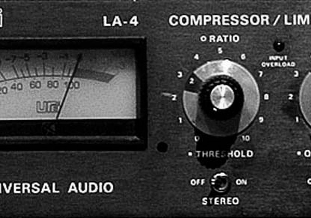
I have always loved optical limiters, especially the classic Teletronix's vacuum tube LA-2A and its "solid- state" sibling, the Universal Audio LA-3A. Both were minimalist in terms of user interface as well as the relatively non-destructive way they processed sound. With just two knobs — input level and gain reduction — and no attack or release controls, it's hard to make a vintage optical limiter sound bad. Much of the secret to their simplicity and success is the optical transmitter and receiver — an electro-luminescent (EL) panel and photo-resistor. The EL panel is driven directly by an audio amplifier — no conversion from AC to DC is required — and has a nearly instantaneous attack time. The photo-resistor primarily determines the attack and release characteristic plus has a bit of "non-linear memory", releasing quickly at first but slowing down as if waiting for the next round of gain reduction commands. Most users agree that optical compression is perfect for vocals, bass and guitars.
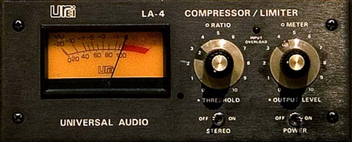
The only "problem" with great vintage compressors is that the prices are out of this world. The new-retro versions are equally pricey, though it's easy to understand the cost — power and audio transformers are not cheap and much of the stuff is hand assembled in this country. Even the LA-4, the bastard stepchild of the family, is a bit pricey. Street price should be $400 to $600 tops but people are asking, and getting, more. What makes a stock LA-4 funky is that it uses an early quad op amp called the RC-4136. This op-amp sucks because, as the input level increases, it slows down, making the LA-4 quite literally dark sounding.
As a service technician, job number one is just to fix stuff and leave whatever creates "character" as part of the box. But a minor repair to an UREI 1176 turned into a "subtle improvement tweak." This intrigued the customer enough to bring over a pair of LA-4s (of which he has eight) for similar treatment. I have this technique of using a square wave oscillator to find bad capacitors, the type of component failure that causes loss of low frequencies. (see the sidebar, "Hunt for Bad Capacitors".) I used the same technique on the 1176, finding a piece of shielded cable in a high-impedance circuit that was ever so slightly attenuating high frequencies.
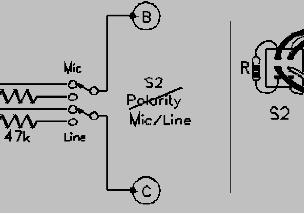
The same approach was taken with the LA-4, tracing the signal from each stage, watching it slow down considerably after passing through four op amps. Figure-1 shows the input stage of the LA-4. Via two amplifiers, U1 and U2, the balanced (differential) input stage eliminates the need for (and the sound of) an input transformer. U3 can be switched for either normal or high (30 dB) gain and is then followed by a "build-out" resistor, R13, that when combined with the photo-resistor, creates a voltage divider/gain manipulator. R13 is a rather high value — 82 k ohm — large enough so that any "stray" capacitance (from U4's input and/or the socket and the circuit board layout) also slows the rise-time of the square wave. I am not bandwidth obsessed, this is just a troubleshooting technique.
What would normally be a simple upgrade is, in this case, hampered by the pin configuration — the RC- 4136 is not compatible with most standard quad op amps, such as the TL074. (Figure-2 details the pin-out variations.) Finding a good op amp with the same low current consumption — 5 mA — is a challenge that requires the following warning:
NOTE: When considering an op amp upgrade, it is important to know, and to monitor, the current consumption of both the original component as well those you will be auditioning. It is not safe to assume that the power supply — for a piece of outboard gear or a console channel strip — will have adequate reserve. In too many cases the power supply is already operating too close to capacity. See Table-1 for a quick comparison.
Since the RC-4136 has no modern pin-compatible quad alternative I decided to use two dual op amps, increasing the options. In order to experiment it was first necessary to create an adapter to re-configure the pins for the dual op amps. After creating a "map" of the here-to-there, a "wire-wrap" IC socket allowed its long legs to be twisted into place. Don't try this at home, kids. There's an easier solution. I tried both the Analog Devices OP275 as well as the Burr-Brown OPA2604, the latter is faster but draws more current, both "attributes" made it prone to oscillation in the LA-4 circuit. There is a fix, but for the moment, I want this to be a plug and play mod. You knew this was leading somewhere, right? Yes, I have successfully developed a retrofit adapter. It's called the EC-4136.
Next issue, I'll go into greater detail about further mods to the LA-4. Visit www.tangible-technology.com for more information about the EC-4136 adapter, plus a whole web site dedicated to audio, from vacuum tubes to digital.
Hunt for Bad Capacitors
Unlike a sine wave that consists of purely the fundamental, square waves are rich in odd-order harmonics, so a single 1 kHz square wave can be used to check the frequency response of a system. This test is particularly useful when checking any equalizer's functionality including the center detent, which if truly "flat" will yield a perfectly square wave. It is also a great test to see if the output transformer requires a termination resistor.
Figure-3 shows a family of square-waves starting with the 500 Hz reference (3-a). Bass roll-off or bad capacitors cause the downward horizontal tilt (3-b), while bass boost tilts the wave in the opposite direction (3-c). Also included are snapshots of treble boost (3-d) and cut (3-e). All "visual effects" can be reproduced using a shelving equalizer. A low-pass (high-cut) filter has a much steeper slope, at least 12 dB/octave, leaving the unique "signature" as seen in Figure-3f).
Notice how the rise time of the square wave is affected. The images will vary depending on the slope of the EQ curve. Boosting the midrange EQ at the same frequency as the oscillator will turn it into a near- sinewave.
